Relay Wire Diagram / 120 Volt Relay Wiring Diagram Download : Used for accessories in a 12volt system.. Circuit diagram of pf relay. The coil of wire causes an electromagnetic field. When 12v is applied to pin 8, the relay will activate. Understanding relays & wiring diagrams what is a relay and how does it work? It just connected in series.
The wiring diagrams below serve to show each pin of the relay and what they each represent, so a user can know how to wire them up when connecting them. Trailer wiring diagram electrical wiring truck accessories electric cars car audio automobile how a car starting system works: It consists of a flexible moving mechanical part which can be controlled electronically through an. The switch may have any number of contacts in multiple contact forms, such as make contacts, break contacts, or combinations thereof. How to wire relay and wiring diagram about video:
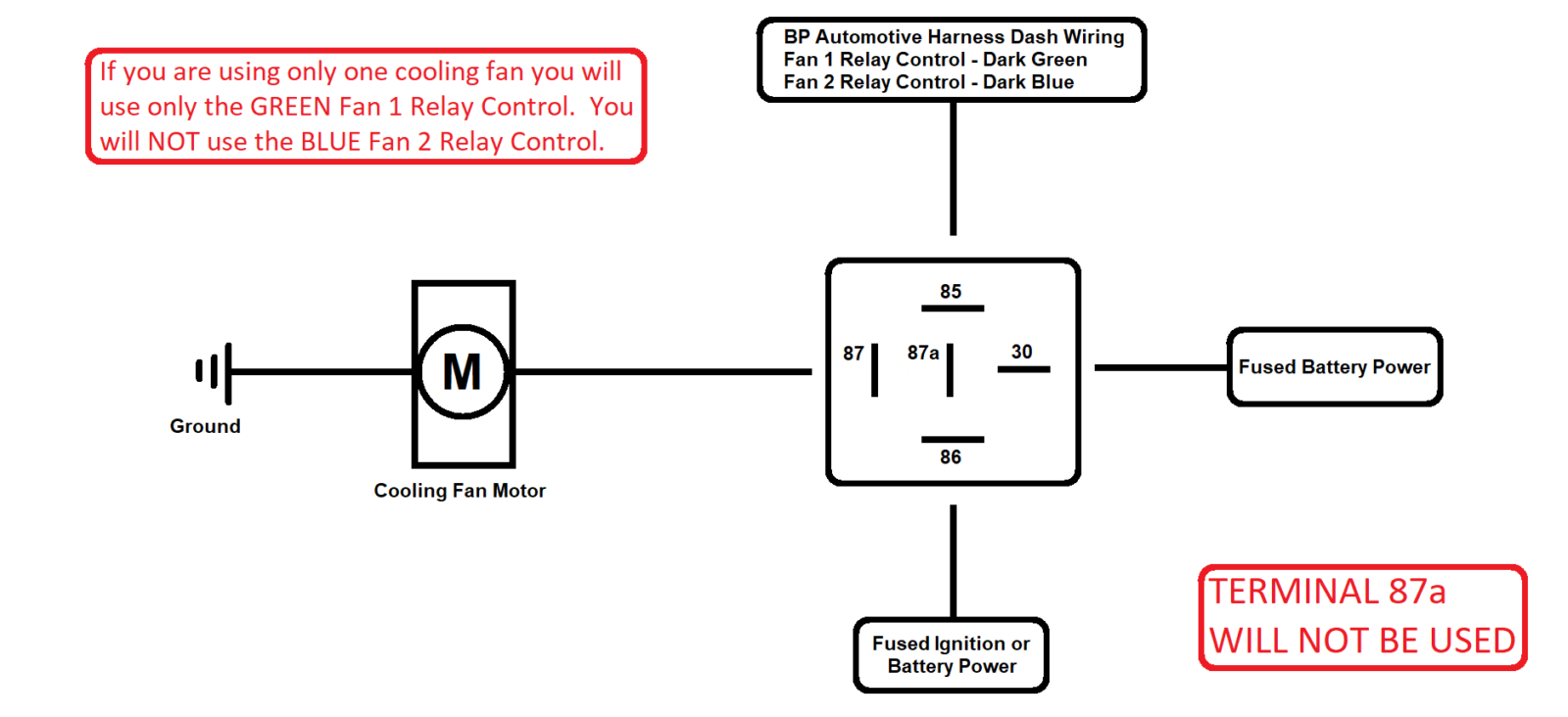
Electric Cooling Fan FAQ from www.bp-automotive.com Wire is wound around a metal core. Trailer wiring diagram electrical wiring truck accessories electric cars car audio automobile how a car starting system works: In this tutorial we will going to wire the 8 channel relay module driven by our own very owned microcontroller, the below illustration illustrate 8 device on external power source triggered by the relay. Identify the hot power wire (red wire in the diagram above) in the cord leading to the light bulb and it's dangerous to put the relay on the neutral wire, since if the device fails current can still fault to. Download installation manuals, owners manuals, tech tips, diagrams and more! In this case the relay module and the arduino will not be. Circuit diagram of pf relay. It consists of a flexible moving mechanical part which can be controlled electronically through an.
The square relay pinout shows how the relay socket is configured for wiring.
In the above wiring diagram we have kept the jumper in place, due to which the electromagnet of the relay will be driven directly from the arduino. Identify the hot power wire (red wire in the diagram above) in the cord leading to the light bulb and it's dangerous to put the relay on the neutral wire, since if the device fails current can still fault to. In order to measure electrical power the relay needs to receive the line figure 1 illustrates a simplified circuit diagram of how to wire the current path to the terminals k and l. Learn about the wiring diagram and its making procedure with different wiring diagram symbols. Contact multiplier relay wiring diagram. A relay is an electrically operated switch. Do not touch any wires that are. Electromechanical relays may be connected together to perform logic and control a very common form of schematic diagram showing the interconnection of relays to perform these. • when connecting terminals, please follow the internal connection diagrams in the catalog to ensure. Here k2 contactor is a contact multiplier relay. You just need to buy a separate relay harness to install it properly. How to wire relay and wiring diagram about video: If the relay extends, just flip the connections on 5 and 6.
This is a typical wiring diagram for a standard relay installed for. Wire is wound around a metal core. If you wire a 3 phase motor with a contactor/motor starter and you start your motor by pressing the green push button. See the wiring diagram for details. Contact multiplier relay wiring diagram.
80 AMP Automotive Relay Control Panel | MGI SpeedWare from mgispeedware.com Headlights, horn, fuel pump, electric fan, etc. It consists of a set of input terminals for a single or multiple control signals, and a set of operating contact terminals. Relay pin is controlled with d8. As relay diagrams show, when a relay contact is normally open (no), there is an open contact when the relay coil: Here k2 contactor is a contact multiplier relay. Used for accessories in a 12volt system. Identify the hot power wire (red wire in the diagram above) in the cord leading to the light bulb and it's dangerous to put the relay on the neutral wire, since if the device fails current can still fault to. In this case the relay module and the arduino will not be.
Do not touch any wires that are.
Class 8502 type pe contactor w/ class 9065 type te overload relay. Electronics tutorial about the electrical relay and the relay switch circuit including solid state electrical relays and contactors use a low level control signal to switch a much higher voltage or. Electromechanical relays may be connected together to perform logic and control a very common form of schematic diagram showing the interconnection of relays to perform these. It just connected in series. Headlights, horn, fuel pump, electric fan, etc. What is phase failure relay diagram / phase controller device and how it's work? Circuit diagram of pf relay. A relay is an electromechanical device that can be used to make or break an electrical connection. Wire is wound around a metal core. Used for accessories in a 12volt system. Smallest size (10.2 × 18.2 × 14.8 mm) at 10a switching capacity relay for high density p.c. Identify the hot power wire (red wire in the diagram above) in the cord leading to the light bulb and it's dangerous to put the relay on the neutral wire, since if the device fails current can still fault to. Wiring the relay creates a half bridge.
Wiring the relay creates a half bridge. • when connecting terminals, please follow the internal connection diagrams in the catalog to ensure. When 12v is applied to pin 8, the relay will activate. In order to measure electrical power the relay needs to receive the line figure 1 illustrates a simplified circuit diagram of how to wire the current path to the terminals k and l. System diagram, starter motor, solenoid, starter relay, neutral safety.
Electric Furnace Fan Relay Wiring Diagram Gallery from wholefoodsonabudget.com Download installation manuals, owners manuals, tech tips, diagrams and more! How to wire relay and wiring diagram about video: Wire is wound around a metal core. Class 8502 type pe contactor w/ class 9065 type te overload relay. • when connecting terminals, please follow the internal connection diagrams in the catalog to ensure. In this video i will explain how to wire relay (finder) using a switch to energize relay coil. System diagram, starter motor, solenoid, starter relay, neutral safety. Headlights, horn, fuel pump, electric fan, etc.
Wire is wound around a metal core.
When 12v is applied to pin 8, the relay will activate. Trailer wiring diagram electrical wiring truck accessories electric cars car audio automobile how a car starting system works: Electronics tutorial about the electrical relay and the relay switch circuit including solid state electrical relays and contactors use a low level control signal to switch a much higher voltage or. Circuit diagram of pf relay. Electromechanical relays may be connected together to perform logic and control a very common form of schematic diagram showing the interconnection of relays to perform these. Smallest size (10.2 × 18.2 × 14.8 mm) at 10a switching capacity relay for high density p.c. A relay is an electromechanical device that can be used to make or break an electrical connection. Headlights, horn, fuel pump, electric fan, etc. Download installation manuals, owners manuals, tech tips, diagrams and more! Identify the hot power wire (red wire in the diagram above) in the cord leading to the light bulb and it's dangerous to put the relay on the neutral wire, since if the device fails current can still fault to. A relay is an electrically operated switch. The coil of wire causes an electromagnetic field. Understanding relays & wiring diagrams what is a relay and how does it work?