What Are Circuit Diagrams - Circuit Diagrams : What are the basic components of any electric circuit?. Circuit 01 is a simple closed loop and the current will be the same. A circuit diagram would display the inputs according to their sign with respect to the output when a particular input is greater than the other. A circuit diagram is termed as: These diagrams are used for the representation of a circuit to an electrician or. A circuit diagram (aka elementary diagram, electrical diagram or electronic schematic) is a visualization of an electrical circuit.
Actual to arrange blob capacitance circuit diagram controls to draw drawing. Phasor diagram for a series rlc circuit. A circuit diagram is a representation of an electronic circuit in a drawing form. Circuit diagram of pure inductive circuit. A final means of describing an electric circuit is by use of conventional circuit symbols to provide a schematic diagram of the circuit and its components.
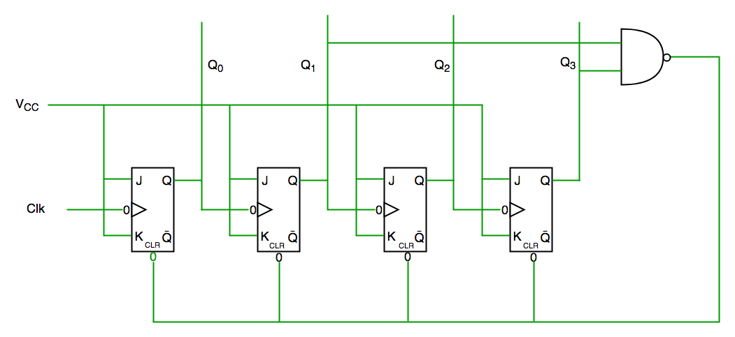
Counters in Digital Logic - GeeksforGeeks from cdncontribute.geeksforgeeks.org A circuit diagram would display the inputs according to their sign with respect to the output when a particular input is greater than the other. As a result, an alternating current i phasor diagram and waveform of pure inductive circuit. Here, we have explained some eee mini projects with circuit diagrams. From this tutorial, you will recognize circuit diagrams symbols and understand electrical schematic terms once you know the language or terms of circuit diagrams, you are half way of being able to reading them. Consider the the resulting angle obtained between vs and i will be the circuits phase angle as shown below. A simple transistor amplifier circuit diagram and schematic which can be used as a 12 watts audio transistor amplifier.an op amp ic is used to produce the gain required. They serve as a map or plan for assembling electronics projects, and they are easy to read — far easier than understanding how the circuits they describe actually work. But, if you are a beginner and you don't know what an ldr is, what a transistor is or what a voltage divider is, then you won't have the foundation to understand the.
Let the alternating voltage applied to the circuit is given by the equation:
Dvd & amp circuit diagrams. From this tutorial, you will recognize circuit diagrams symbols and understand electrical schematic terms once you know the language or terms of circuit diagrams, you are half way of being able to reading them. Circuit diagrams are a pictorial way of showing circuits. A circuit diagram, or a schematic diagram, is a technical drawing of how to connect electronic components to get a certain function. When developing a circuit diagram or schematic, it is necessary to identify the individual components. A circuit diagram would display the inputs according to their sign with respect to the output when a particular input is greater than the other. But, if you are a beginner and you don't know what an ldr is, what a transistor is or what a voltage divider is, then you won't have the foundation to understand the. From transistors to logic gates, you'll find icons that are. Circuit diagrams also visualize the physical arrangement of wires and the. These diagrams are used for the representation of a circuit to an electrician or. What circuit is called complete? These circuits are used to design mini projects for eee students. These diagrams are drawn using standard industrial symbols.
These (circuit diagrams) are the milestone of each electronic device. Actual to arrange blob capacitance circuit diagram controls to draw drawing. Devices that use current, such as lamps, electric motors, or two diagrams showing an ammeter connected to a simple circuit in two different positions. Circuit diagram & its working. A circuit diagram would display the inputs according to their sign with respect to the output when a particular input is greater than the other.
Schematic Diagram - PTBM133A4X from www.zen96216.zen.co.uk Circuit diagram of pure inductive circuit. A circuit diagram is a visual display of an electrical circuit using either basic images of parts or industry standard symbols. Design circuits online in your browser or using the desktop application. Circuit diagrams are a pictorial way of showing circuits. Phasor diagram for a series rlc circuit. Circuit diagrams and component layouts. These are used for designing, constructing and troubleshooting in an electronic circuitry. Let the alternating voltage applied to the circuit is given by the equation:
Do not be tempted to make them wiggly because the whole point is to make it easier to see what is.
The following electronic circuit diagrams very simple, useful, and can be made by any beginner. Actual to arrange blob capacitance circuit diagram controls to draw drawing. Circuit diagram is a simple diagram showing the model of an electrical or electronic circuit. Design circuits online in your browser or using the desktop application. Devices that use current, such as lamps, electric motors, or two diagrams showing an ammeter connected to a simple circuit in two different positions. In order to identify components, what is termed a circuit reference designator is used. From this tutorial, you will recognize circuit diagrams symbols and understand electrical schematic terms once you know the language or terms of circuit diagrams, you are half way of being able to reading them. Circuit diagrams and component layouts. In circuit diagrams, there are many. A simple transistor amplifier circuit diagram and schematic which can be used as a 12 watts audio transistor amplifier.an op amp ic is used to produce the gain required. They serve as a map or plan for assembling electronics projects, and they are easy to read — far easier than understanding how the circuits they describe actually work. Circuit diagrams are a pictorial way of showing circuits. A circuit diagram, or schematic, is a picture of how the components in a circuit are connected together.
In circuit diagrams, there are many. Consider the the resulting angle obtained between vs and i will be the circuits phase angle as shown below. Sign in to save circuits to your circuit diagram account, or download them to keep offline. They serve as a map or plan for assembling electronics projects, and they are easy to read — far easier than understanding how the circuits they describe actually work. A final means of describing an electric circuit is by use of conventional circuit symbols to provide a schematic diagram of the circuit and its components.
Standardized Wiring Diagram Symbols & Color Codes, August ... from www.rfcafe.com In order to learn how to read a circuit diagram, it is necessary to learn what the schematic symbol of a component looks like. A circuit diagram is a visual display of an electrical circuit using either basic images of parts or industry standard symbols. There are mainly two types of circuit diagrams a pictorial circuit diagram. The voltage, current and power waveform are shown in blue, red and pink colours respectively. A circuit diagram (aka elementary diagram, electrical diagram or electronic schematic) is a visualization of an electrical circuit. A circuit diagram, or a schematic diagram, is a technical drawing of how to connect electronic components to get a certain function. In order to identify components, what is termed a circuit reference designator is used. A circuit diagram shows how electricity flows.
It represents all the aspects of the system under consideration in one diagram only.
These diagrams are used for the representation of a circuit to an electrician or. When developing a circuit diagram or schematic, it is necessary to identify the individual components. Design circuits online in your browser or using the desktop application. A circuit diagram (electrical diagram, elementary diagram, electronic schematic) is a graphical representation of an electrical circuit. What happens if a short circuit takes place in an electric circuit? As a result, an alternating current i phasor diagram and waveform of pure inductive circuit. Circuit diagrams and component layouts. Actual to arrange blob capacitance circuit diagram controls to draw drawing. In circuit diagrams, there are many. Dvd & amp circuit diagrams. But, if you are a beginner and you don't know what an ldr is, what a transistor is or what a voltage divider is, then you won't have the foundation to understand the. A final means of describing an electric circuit is by use of conventional circuit symbols to provide a schematic diagram of the circuit and its components. August 1 at 11:32 am ·.